Cisco MPLS Layer3 VPN LAB
5/5/2025
In this Post , I am giving example of a complete MPLS Layer 3 Lab configuration using GNS3
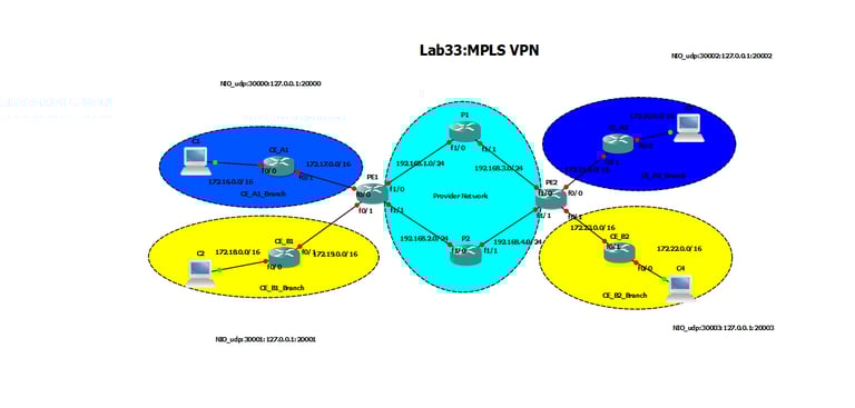
Diagram:
Preliminary Task:
Connect the network as shown in the diagram, and assign the ip addresses as explained in the above figure.
Configure Loopback addresses for PE & P routers as follows: PE1: 1.1.1.1/32, PE2: 2.2.2.2/32, P1: 3.3.3.3/32 , P2:4.4.4.4/32
Task 1:
Configure two VRFs (CE_A & CE_B) on each of the PE routers, and put the PE-CE interfaces into the equivalent interfaces:
!PE1
ip vrf CE_A
rd 1:1
route-target both 1:1
!
ip vrf CE_B
rd 2:2
route-target both 2:2
!
int fa0/0
ip vrf forwarding CE_A
ip address 172.17.0.1 255.255.0.0
!
int fa0/1
ip vrf forwarding CE_B
ip address 172.19.0.1 255.255.0.0
!PE2
ip vrf CE_A
rd 1:1
route-target both 1:1
!
ip vrf CE_B
rd 2:2
route-target both 2:2
!
int fa0/0
ip vrf forwarding CE_A
ip address 172.21.0.1 255.255.0.0
!
int fa0/1
ip vrf forwarding CE_B
ip address 172.23.0.1 255.255.0.0
Task 2:
Configure OSPF 10 between the PE & CE routers and ensure the OSPF adjacencies have been established.
!CE_A1
router ospf 10
network 172.16.0.0 0.0.255.255 area 0
network 172.17.0.0 0.0.255.255 area 0
!CE_B1
router ospf 11
network 172.18.0.0 0.0.255.255 area 0
network 172.19.0.0 0.0.255.255 area 0
!PE1
router ospf 10 vrf CE_A
log-adjacency-changes
network 172.17.0.0 0.0.255.255 area 0
!
router ospf 11 vrf CE_B
log-adjacency-changes
network 172.19.0.0 0.0.255.255 area 0
!CE_A2
router ospf 10
network 172.20.0.0 0.0.255.255 area 0
network 172.21.0.0 0.0.255.255 area 0
!CE_B2
router ospf 11
network 172.22.0.0 0.0.255.255 area 0
network 172.23.0.0 0.0.255.255 area 0
!PE2
router ospf 10 vrf CE_A
log-adjacency-changes
network 172.21.0.0 0.0.255.255 area 0
!
router ospf 11 vrf CE_B
log-adjacency-changes
network 172.23.0.0 0.0.255.255 area 0
Task 3:
Configure OSPF process 1 between all the routers in the provider network and don't forget to include loopback interfaces advertisement.
!PE1
router ospf 1
network 1.1.1.1 0.0.0.0 area 0
network 192.168.1.0 0.0.0.255 area 0
network 192.168.2.0 0.0.0.255 area 0
!PE2
router ospf 1
network 2.2.2.2 0.0.0.0 area 0
network 192.168.3.0 0.0.0.255 area 0
network 192.168.4.0 0.0.0.255 area 0
!P1
router ospf 1
network 3.3.3.3 0.0.0.0 area 0
network 192.168.3.0 0.0.0.255 area 0
network 192.168.1.0 0.0.0.255 area 0
!P2
router ospf 1
network 4.4.4.4 0.0.0.0 area 0
network 192.168.2.0 0.0.0.255 area 0
network 192.168.4.0 0.0.0.255 area 0
Verification:
P1#show ip ospf neighbor
Neighbor ID Pri State Dead Time Address Interface
1.1.1.1 1 FULL/DR 00:00:34 192.168.1.2 FastEthernet1/0
2.2.2.2 1 FULL/BDR 00:00:34 192.168.3.1 FastEthernet1/1
P2#show ip ospf neighbor
Neighbor ID Pri State Dead Time Address Interface
2.2.2.2 1 FULL/DR 00:00:31 192.168.4.1 FastEthernet1/1
1.1.1.1 1 FULL/BDR 00:00:38 192.168.2.2 FastEthernet1/0
Task 4:
Configure BGP AS 100 between the PE routers, and use loopback interface as the update source.
!PE1
router bgp 100
no synchronization
bgp log-neighbor-changes
neighbor 2.2.2.2 remote-as 100
neighbor 2.2.2.2 update-source Loopback0
!PE2
router bgp 100
no synchronization
bgp log-neighbor-changes
neighbor 1.1.1.1 remote-as 100
neighbor 1.1.1.1 update-source Loopback0
Verification:
PE1#show ip bgp summary
BGP router identifier 1.1.1.1, local AS number 100 BGP table version is 1, main routing table version 1
Neighbor V AS MsgRcvd MsgSent TblVer InQ OutQ Up/Down State/PfxRcd
2.2.2.2 4 100 2 2 0 0 0 00:00:29 0
Task 5:
Activate MP-BGP neighborhood between the PE routers, in order to advertise the VRF customer routes later with their route distinguisher.
!PE1
router bgp 100
address-family vpnv4
neighbor 2.2.2.2 activate
neighbor 2.2.2.2 send-community extended
!
!PE2
router bgp 100
address-family vpnv4
neighbor 1.1.1.1 activate
neighbor 1.1.1.1 send-community extended
Verification:
PE1#show ip bgp vpnv4 all summary
BGP router identifier 1.1.1.1, local AS number 100 BGP table version is 1, main routing table version 1
Neighbor V AS MsgRcvd MsgSent TblVer InQ OutQ Up/Down State/PfxRcd
2.2.2.2 4 100 9 9 1 0 0 00:00:25 0
Task 6:
Redistribute Mutually between the OSPF and the BGP VPNv4 on PE1 & PE2:
!PE1/PE2
router bgp 100
address-family ipv4 vrf CE_A
redistribute ospf 10 vrf CE_A match internal external 1 external 2
address-family ipv4 vrf CE_B
redistribute ospf 11 vrf CE_B match internal external 1 external 2
!
router ospf 10 vrf CE_A
redistribute bgp 100 subnets
!
router ospf 11 vrf CE_B
redistribute bgp 100 subnets
Verification:
!CE_A1#show ip route
C 172.17.0.0/16 is directly connected, FastEthernet0/1 C 172.16.0.0/16 is directly connected, FastEthernet0/0
O IA 172.21.0.0/16 [110/2] via 172.17.0.1, 00:03:28, FastEthernet0/1
O IA 172.20.0.0/16 [110/3] via 172.17.0.1, 00:03:28, FastEthernet0/1
!CE_B1#show ip route
Gateway of last resort is not set
C 172.19.0.0/16 is directly connected, FastEthernet0/1 C 172.18.0.0/16 is directly connected, FastEthernet0/0
O IA 172.23.0.0/16 [110/2] via 172.19.0.1, 00:03:57, FastEthernet0/1
O IA 172.22.0.0/16 [110/3] via 172.19.0.1, 00:03:57, FastEthernet0/1
Task7:
Enable MPLS on all interfaces within the provider network
!PE1/PE2/P1/P2
int fa1/0
mpls ip
!
int fa1/1
mpls ip
Verification:
PE2#sh mpls ldp neighbor
Peer LDP Ident: 3.3.3.3:0; Local LDP Ident 2.2.2.2:0 TCP connection: 3.3.3.3.39927 - 2.2.2.2.646
State: Oper; Msgs sent/rcvd: 11/11; Downstream Up time: 00:00:45
LDP discovery sources:
FastEthernet1/0, Src IP addr: 192.168.3.2 Addresses bound to peer LDP Ident: 192.168.1.1 192.168.3.2 3.3.3.3
Peer LDP Ident: 4.4.4.4:0; Local LDP Ident 2.2.2.2:0 TCP connection: 4.4.4.4.20674 - 2.2.2.2.646
State: Oper; Msgs sent/rcvd: 11/11; Downstream Up time: 00:00:24
LDP discovery sources:
FastEthernet1/1, Src IP addr: 192.168.4.2 Addresses bound to peer LDP Ident: 192.168.2.1 192.168.4.2 4.4.4.4
PE1#show mpls ldp neighbor
Peer LDP Ident: 3.3.3.3:0; Local LDP Ident 1.1.1.1:0 TCP connection: 3.3.3.3.41239 - 1.1.1.1.646
State: Oper; Msgs sent/rcvd: 12/13; Downstream Up time: 00:01:40
LDP discovery sources:
FastEthernet1/0, Src IP addr: 192.168.1.1 Addresses bound to peer LDP Ident: 192.168.1.1 192.168.3.2 3.3.3.3
Peer LDP Ident: 4.4.4.4:0; Local LDP Ident 1.1.1.1:0 TCP connection: 4.4.4.4.60863 - 1.1.1.1.646
State: Oper; Msgs sent/rcvd: 12/12; Downstream Up time: 00:01:14
LDP discovery sources:
FastEthernet1/1, Src IP addr: 192.168.2.1 Addresses bound to peer LDP Ident: 192.168.2.1 192.168.4.2 4.4.4.4
PE1#show mpls forwarding-table
Local Outgoing Prefix Bytes Label Outgoing Next Hop Label Label or VC or Tunnel Id Switched interface
16 17 2.2.2.2/32 0 Fa1/0 192.168.1.1
17 2.2.2.2/32 0 Fa1/1 192.168.2.1
17 Pop Label 3.3.3.3/32 0 Fa1/0 192.168.1.1
18 Pop Label 4.4.4.4/32 0 Fa1/1 192.168.2.1
19 Pop Label 192.168.3.0/24 0 Fa1/0 192.168.1.1
20 Pop Label 192.168.4.0/24 0 Fa1/1 192.168.2.1
21 No Label 172.16.0.0/16[V] 0 Fa0/0 172.17.0.2
22 No Label 172.17.0.0/16[V] 0 aggregate/CE_A
23 No Label 172.18.0.0/16[V] 0 Fa0/1 172.19.0.2
24 No Label 172.19.0.0/16[V] 0 aggregate/CE_B
Ping Between PCs on CE_A should be working & on CE_B should be working as well.
Waleed Hashim Ali Adlan
CCIE#41999/HCIE#14518
Email: network@networkplus-tc.com
Phone: +249913861072/+249119641984/+249100111624
© 2024. All rights reserved.